Since release 7u40, Java can run on LEGO Mindstorms EV3. In this post the JMC Team will explore how to use Java Mission Control to monitor Java applications running on Mindstorms. This post is a guest post by the JMC Team.
What We Have Done
Our primary goal was to show that we can monitor a Java application running on a Java SE embedded platform over JMX.
We started off by unpacking our LEGO Mindstorms kit and built the demo robot which was a good way to get to know the components. A simple demo program was present in the default firmware so it was quite easy to get it to run.

When we had familiarized ourselves with the different sensors and motors we moved on to actually running Java on the system. The leJOS project provides a Linux distribution that can run on Mindstorms and a set of libraries to control just about anything you can connect to the system.
After installing leJOS we verified that we could run Java programs and monitor them using Java Mission Control. Finally we wrote a program that allowed us to control the robot using the MBean management functionality in Java Mission Control.
Running Java programs on Mindstorms
What you need:
- LEGO Mindstorms EV3
- A MicroSD card
- An SD card reader
- A USB WiFi adapter that is supported by leJOS
We used a Netgear WNA1100 adapter which is identical to the official LEGO WiFi adapter. A list of alterative adapters can be found at http://www.rjmcnamara.com/lego-mindstorms-ev3/mindstorms-ev3-compatible-wi-fi-dongles/ but we have not tested any of them. It is worth pointing out that the adapter we used sticks out quite a bit so it has to be considered when choosing what to build.
- A WiFi network with a DHCP server
Just about any WiFi router should work.
- A Linux computer to use for writing the leJOS system to the SD card
If you don’t have a Linux computer you can follow the guide at http://sourceforge.net/p/lejos/wiki/Running%20Ubuntu%20with%20VirtualBox/ to get a virtual Linux system.
- A computer for developing and compiling Java programs.

Installing leJOS
To run leJOS you need a bootable SD card with leJOS on it. When you turn on the Mindstorms system with this card inserted it will boot the leJOS distribution. If the SD card slot is empty it will boot the default LEGO system. This is very nice since you don’t have to make any permanent changes to the firmware. You only have to remove the card in order to make it behave as a normal Mindstorms system again.
A handy tip is to attach a small piece of tape to the SD card. This makes it much easier to remove the card from the Mindstorms system if you need to update it later or if you want to keep several cards with different contents.
To install leJOS on an SD card, follow the guide at http://sourceforge.net/p/lejos/wiki/Creating%20a%20bootable%20SD%20card/.
Note that when you insert the SD card into the Linux system for formatting and writing, it is not always clear which device the SD card is using. If the card was mounted automatically you can use the command mount to see which devices are mounted. You can also use the command dmesg to see messages that come when hardware changes are detected. In any event, take care not to select the device for your hard disk.
When the SD card is complete you can start using it:
- Insert the WiFi USB stick into the USB port on the Mindstorms system
- Insert the SD card into the SD card slot on the Mindstorms brick and turn it on
If everything worked correctly you will after a while see the leJOS logo and one or two IP addresses on the screen. One is for USB and Bluetooth networking and the other is for WiFi.

Connect to the WiFi IP address using ssh and login as root with no password. This will give you a pretty normal Linux prompt from where you can run your programs.
You can try running a demo program:
cd /home/root/lejos/samples
jrun EV3HelloWorld
This should result in some beeping and blinking.
Development environment
If you follow the instructions at http://sourceforge.net/p/lejos/wiki/Developing%20with%20leJOS/ then you will get an Eclipse development environment where you can do everything from within Eclipse.
Minimum requirements
If you can’t or don’t want to do everything from within Eclipse then you can set up your own environment. For a minimal setup all you need to do is to get hold of the ev3 library.
The first option is to get the latest source files from git. You can do this either by running git clone git://git.code.sf.net/p/lejos/ev3 lejos-ev3 or, if you don’t have git installed, downloading a snapshot of the code from http://sourceforge.net/p/lejos/ev3/ci/master/tree/. The subdirectories contains various libraries and demo projects complete with Eclipse project files. The ev3classes subdirectory contains the source code for the leJOS API so import at least that into your favorite development environment.
You should preferably build the DbusJava and ev3classes projects with ant. This will give you an ev3classes.jar file which should be placed in /home/root/lejos/lib on your Mindstorms system so that you have the same version of the library when you run your programs.
The second option is to take the ev3classes.jar file from the leJOS installation and add it to your classpath. You can find this jar file on your Mindstorms system in /home/root/lejos/lib. Note however that the ev3classes.jar file that is distributed with the leJOS installer is not necessarily the latest so we recommend getting the source code from git and building it yourself if you can.
Development process
In short, the development process consists of these stages:
- Write a program and compile it on your development system
- Upload the class or jar files to the Mindstorms system
- Run the program on the Mindstorms system
If you followed the guide on the lejos wiki then you can follow their instructions. Otherwise, you can use your favorite scp application to transfer files and your favorite ssh terminal to run your programs.
Whichever way you choose, start off with a simple program like this one:
import lejos.hardware.Button;
import lejos.hardware.LCD;
public class HelloWorld {
public static void main(String[] args) throws Exception {
LCD.clear();
LCD.drawString(“Hello World”, 0, 5);
Button.waitForAnyPress();
LCD.clear();
LCD.refresh();
}
}
Compile the program and create a jar file with the class:
javac -cp ev3classes.jar HelloWorld.java
jar cvf HelloWorld.jar HelloWorld.class
Copy the jar file to the Mindstorms system using scp and start it from an ssh terminal:
jrun -cp HelloWorld.jar HelloWorld
Connecting Java Mission Control to a remote Java process
Java Mission Control is a tool for monitoring and analyzing Java processes. It has been bundled together with JDK since version 7u40. Java Mission Control uses JMX to communicate with remote Java processes. To enable the management agent on a Java process you can add the following parameters when starting it:
-Dcom.sun.management.jmxremote=true -Dcom.sun.management.jmxremote.port=7091 -Dcom.sun.management.jmxremote.authenticate=false -Dcom.sun.management.jmxremote.ssl=false
You can select just about any free port number instead of 7091. If you are running multiple Java processes on the same system then you need to use different ports for each process. Depending on how the leJOS system detects which IP address is the primary one, you may also have to add the following parameter:
-Djava.rmi.server.hostname=The IP address of the Mindstorms WiFi adapter
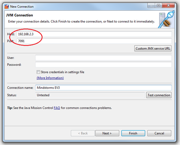
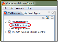
Once the Java process is up and running you can connect to it using Java Mission Control. Add a connection to the Mindstorms IP address and the port number that you chose. Expand your new connection in the JVM browser view and open a JMX Console on the MBean Server.


If everything worked as it should you will see a console window displaying the status of the Java process.

This procedure is the same for any remote Java process that you want to monitor. Java Mission Control can auto-detect Java processes that can be monitored through a protocol called JDP. You can read more about JDP at https://hirt.se/blog/?p=388.
Monitoring and controlling Mindstorms using MBeans
Now you have a Java process running on the Mindstorms system and you can communicate with it using JMX. This allows you to see a lot of information about what the Java process is doing. The next step is to monitor and control the sensors and motors connected to the Mindstorms system. To do this we implement a custom MBean that expose the leJOS libraries.
You can read more about MBeans and MXBeans at http://docs.oracle.com/javase/tutorial/jmx/mbeans/index.html.
Creating an MBean
An MBean is basically a Java class that implements an interface. Start off by creating the interface:
public interface MotorMXBean {
public void moveForward();
public void stopMotor();
public int getSpeed();
public void setSpeed(int speed);
}
Then create a class implementing the interface:
import lejos.hardware.motor.NXTRegulatedMotor;
public class Motor implements MotorMXBean {
final NXTRegulatedMotor m_motor;
public Motor(NXTRegulatedMotor motor) {
m_motor = motor;
}
@Override
public void moveForward() {
m_motor.forward();
}
@Override
public void stopMotor() {
m_motor.stop();
}
@Override
public int getSpeed() {
return m_motor.getSpeed();
}
@Override
public void setSpeed(int speed) {
m_motor.setSpeed(speed);
}
}
This exposes a small subset of everything that can be done but it will give you an idea of how things work. You don’t have to expose the leJOS library methods directly, often it can be more useful to have more complex operations like ”find a ball” or monitor values like ”number of balls found”.
With the MBeans implemented, it is time to create an instance and register it with the platform MBean server.
import java.lang.management.ManagementFactory;
import javax.management.MBeanServer;
import javax.management.ObjectName;
public class MBeanRunner {
public static void main(String[] args) throws Exception {
MBeanServer mbs = ManagementFactory.getPlatformMBeanServer();
Motor m = new Motor(lejos.hardware.motor.Motor.B);
ObjectName name = new ObjectName(“lejostest:name=MotorB”);
mbs.registerMBean(m, name);
System.out.println(“Server is running. Press enter to exit”);
System.in.read();
}
}
This is a very simple program that doesn’t do anything on its own. It registers a motor controller with the MBean server and waits for commands. Compile the classes and place them on the Mindstorms system. Connect a motor to port B on the Mindstorms system and start the program:
jrun -cp Test.jar -Dcom.sun.management.jmxremote=true -Djava.rmi.server.hostname=192.168.2.3 -Dcom.sun.management.jmxremote.port=7091 -Dcom.sun.management.jmxremote.authenticate=false -Dcom.sun.management.jmxremote.ssl=false MBeanRunner
Start Java Mission Control and connect to the Mindstorms system. Go to the MBean Browser and locate the lejostest/MotorB MBean. Go to the Operations tab, select moveForward and click on Execute:

The motor should start running. Go to the Attributes tab and you will see a list of values for all attributes that are exposed with getter methods. Attributes that have setter methods can be set so try clicking on the value for the speed attribute, enter a new value and finish with enter:

The motor should now change speed. To stop the motor, go back to the operations tab and execute the stopMotor operation.
Conclusion
If you have followed this guide you will have accomplished three things:
- Running Java programs on a Mindstorms system
- Monitoring a remote Java process with Java Mission Control
- Exposing application specific data and operations in an MBean
All of these things can be done independently. You can run Java programs on Mindstorms without monitoring them, any program running on a supported JVM can be monitored with Java Mission Control, and there are other methods of monitoring MBeans.
Enjoy.
More information about Java Mission Control can be found at http://www.oracle.com/missioncontrol.
More information about leJOS can be found at http://www.lejos.org/ and at http://sourceforge.net/projects/lejos/.


